Usage for Tiny PIC bootloader
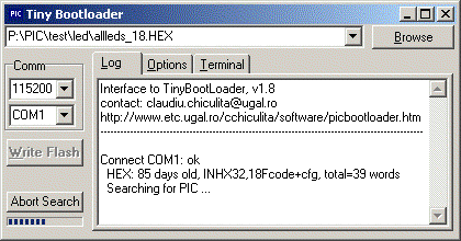
After you browse or enter the name of the hex file, select the COM port and
baud rate:
- You can keep the TinyBootloader interface opened, then click WriteFlash, or
double-click the tray icon, and after that reset (or power-up) the PIC. If your
program is continuously sending serial data to PC, (that will be interpreted
as a bootloader response) use the second method:
- first press PIC reset,
click WriteFlash, then release PIC reset;
- Use a hardware (RTS) or
software reset (codes to send first).
If all things are set up properly the program will be loaded into the pic and
executed.
Write Flash
 |
-
Connects to the specified port with the chosen baud rate
(both are editable, any value can be typed in)
-
Reads and analyzes the hex file, determines if it's a 16F or 18F
code, determine the size, eeprom and
config data; check for a goto in the first 4 words, and gives warnings if
necessary;
-
Pings the serial port (with the "Code sent by PC for
activation") at a rate given by "Timeout" until there is a response from the PIC or
until the "SearchDelay" timeout will expire.
-
When a response from the PIC is received the PIC type is
identified and the user program written.
(no eeprom or config words are written. if needed, this can be done by using
one of the available commands).
|
Commands
 |
Command line parameter: hex filename to be written.
When using a command line parameter writing flash will start
automatically.
|
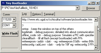
Some commands that can be written in the Log window:
| ? |
help |
| ontop |
keep the window on top of the others |
| logdetails |
lists detailed stuff happening inside (used only for debugging) |
| clearallflash |
clears all flash except the bootloader (actually it fills
all flash with FFh) |
| writeeeprom <addr> <dat> |
writes the byte <dat> at the address <addr> (numbers can be
either dec or hex)
eg: writeeeprom 0 b6h
-
writes B6h in the first eeprom location |
| writeconfig <adrLow> <dat> |
only for 18F; writes the configuration byte <dat> at the
address 300000h+<addrLow>
eg: writeconfig 3 FFh
-
activates WDT |
These commands are very rarely used, so it is possible not to work properly
for all devices.
Options
 |
-
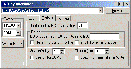
List of codes to send first: could be interpreted by a user
program as a reset (or activate bootloader command);
-
"SearchDelay" is the amount of time the
application will try to contact the pic.
-
"Timeout" is the ping interval; also it acts as a
timeout for all serial operations. If you expect large
communication delays, you should increase this (but don't forget to
also increase the timeout in tinybld)
|
 |
- Reset could also be performed by hardware, "Reset PIC using RTS
line". There are several ways to do it; some require that after
reset the RTS should remain low, others prefer "RTS to remain
active"
|
Terminal
 |
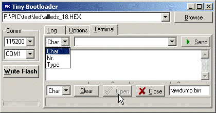
A rudimentary Terminal, with the following
possibilities:
- Display received data as text, hex dump, character codes or
graphic.
- Automatically saves raw data to the specified file (rewrite at
every terminal activation).
- Can send:
- ascii string
- one by one characters as you type
- decimal or hex codes
- It has a limited (adjustable) display buffer (default 10k)
|
|
|
What do you need
Hardware
- A look at the PIC quick reference could
be useful.
- An external programmer is needed (only) the first time in order to write the bootloader into the PIC
- On your board, you must have the PIC (pins TX,RX) connected to the serial port of the PC
(pins Rx,Tx), usually using a MAX232 level converter:

Bootloader Software
- You can use one of the provided .hex files or
- Modify source and assemble it using MPASM IDE
- PIC16,18: Modify "xtal", "baud", and
configuration bits to what you need; assemble it
(for example with .\MPLAB\MCHIP_Tools\Mpasmwin.exe);
- dsPIC: modify "Fcy", "baud" and configuration bits.
- Write the HEX with a PIC programmer; put the PIC on you board and connect it to the PC
serial port.
User Software
The software you write requires no other modification. There are few
things to consider:
- If you write your software in assembler the program must have in the first 4 words of
memory a GOTO to the start of the main program. This is how most of the ASM
programs look anyway. So in assembler it should look something like this:
| PIC16F |
PIC16F |
PIC18F |
org 0
;clrf STATUS
clrf PCLATH
goto Main |
org 0
;clrf STATUS
pagesel Main
goto Main |
org 0
goto Main
|
- If you use a (C/Basic/...) compiler, some of them may require a special
directive to allows
coexistence with a bootloader; but then again, most of them will work without
specifying anything.
Advanced topics
Modifying it for other devices
- Verify that the PIC support flash self-write:
In the datasheet verify that there is a (sub)chapter concerning "Writing to
Flash program memory".
- Find another PIC that has similar features and that has the source code
(.asm or .s) available. Open both PIC datasheets, at the chapter referring
to Flash Write and make sure that the info referring to erase block size and
program block size is the same.
- In the piccodes.ini file you have to
either:
- use an existing entry, if you find one that matches the type
of PIC and the amount of flash; no modifications will be necessary, just
take the id-code (the number in the first column);
- add a new entry, by adding a new id-code, the type of PIC, a
description, amount of flash, amount of eeprom.
- Hint: look into the datasheet of an existing PIC to see how to write
the flash amount;
- Modify the source for your PIC, using the id-code obtained at the
previous step
- for dsPICs, directly in the source modify:
.equ IdTypePIC,ZZZ
- for PIC16 and 18, make the addition in
the icdpictypes.inc
file.
Adding more stuff to the bootloader
The bootloader was designed to fit in 96+4 words. On most devices (pic16,
pic18) there is almost no room to extend the bootloader by adding more
instructions. Extending it is possible by modifting tinybld.ini to use a size of
132 and double that number in asm source.
Critics and suggestions at: 


![]()